The discussion today is about the Internet Protocol (IP) Configuration. The discussion dwells on the understanding of IP addresses (composition of an IP address, configuration process, and its types).
About the IP Address
A network is composed of different nodes. Every node of a network should have an IP address so that they can communicate with each other. IP address has different versions, but commonly used today is the IPv4. But due to the IP address exhaustion in February 03, 2011, IPv6 is now available to use.
IPv4 has a 32 bit address. It has 4 groups of 4-digit binary addresses. Every group consists of 8 bit binary address.
________ . ________ . ________ . _________
1st octet 2nd octet 3rd octet 4th octet
8 bits 8 bits 8 bits 8 bits
On the other hand, IPv6 consists of 128 bit address. It has 8 groups of 4-digit hexadecimal addresses. IPv4 and IPv6 is not interoperable, meaning that two different computers with different IP version cannot communicate.
Network Address and Host Address
IP address can be divided into two address or ID: the Network Address/Network ID and the Host Address/Host ID. Basically, the network address occupies the first or higher octet, while the host address occupies the remaining octets.
N . H . H . H (N = network address, H = host address)
And in order to delay the occurrence of IPv4 exhaustion, IP classes was introduced to allocate network addresses and host addresses accordingly.
Class A 0 N . H . H . H 2^7 networks, 2^24 hosts (possible combinations)
Class B 10 N . N . H . H 2^14 networks, 2^16 hosts (possible combinations)
Class C 110 N . N . H . H 2^21 networks, 2^8 hosts (possible combinations)
Class D 1110 N . N . N . H
Class E 11110 . H . H . H
IP classes have ranges so that IP addresses can be easily identified, and to know what are the possible address can be. These ranges can be used publicly (networks).
Class A 1 . 0 . 0 . 0 - 127 . 255 . 255 . 255
Class B 128 . 0 . 0 . 0 - 191 . 255 . 255 . 255
Types of IP
Static IPs are only used for private networks. The user of a computer can assign an IP address to a particular computer in a private network.
How to change an IP address statically:
ifconfig <interface> <IP address> netmask <netmask> broadcast <bcast>
i.e.
ifconfig eth0 172.16.9.6 netmask 255.255.255.0 broadcast 172.16.9.255
Dynamic IPs allows a router to assign an IP address to a computer.
How to change an IP dynamically:
dhclient <interface>
i.e.
dhclient eth0
Subnet Mask determines the network address from the host address.
Subnet Mask (Default)
Class A N . H . H . H 255.0.0.0
Class B N . N . H . H 255.255.0.0
PROBLEM STATEMENT
The students need to design a network to establish connection with at least two local hosts. The network can be implemented using the concept of IP configuration discussed above. The design should be done using the Network Simulator software.
GUIDES ON SOLVING THE PROBLEM
Designing a Network using Network Simulator (with 2 hosts)
The activity done today was to connect to two different networks together. The first network composed of a computer connected to a router, and same for the second network. To able to connect the two networks, there should be another network connecting the two routers. Thus, we assign a different network address for that network.
To be able to connect the two routers to the new network, let's say has an IP address of 192.168.0.X, Router1 should have an IP address with this format: 192.168.0.1, and Router2 with 192.168.0.2. Since, now they belong to the same network, they can now communicate to each other using ping command.
Here is the process on how to do these:
1. Open a terminal and type this command to be able to use the Network Simulator: java -jar netsim-3.0.jar. (If you don't have this package, download it from jachermocilla.org :D)
2. Start creating the network like this! :)
Configure the other router (Router 2).
As seen at the screenshot, it can be said that the three hosts are connected to each other using a switch. Just ensure to configure the proper IP addresses of the computers and the routers, and have a correct connection to each other, so that the connection would be successful. :)))
LEARNING AND INSIGHTS
The discussion and activity elaborates the importance and use of IP addresses. Also, the establishment of connection between different computers using the IP configuration concepts is demonstrated by the Network Simulator software so well. I am fascinated with this activity because I am not that knowledgeable in these areas. And the fact that the series of numbers in every IP address symbolizes something, have helped me to understand it better. =)
CONCLUSION
The students learn how to configure local hosts using their respective IP addresses to establish connect with each other. The established connection can be via the router, a server or a switch. Also, the Network Simulator give a concrete example on how to do the configuration virtually. And lastly, it show how the IP addresses are important in every computer around the world.
C:Users/regina>Connection established!
C:Users/regina>Bye! :D
________ . ________ . ________ . _________
1st octet 2nd octet 3rd octet 4th octet
8 bits 8 bits 8 bits 8 bits
On the other hand, IPv6 consists of 128 bit address. It has 8 groups of 4-digit hexadecimal addresses. IPv4 and IPv6 is not interoperable, meaning that two different computers with different IP version cannot communicate.
Network Address and Host Address
IP address can be divided into two address or ID: the Network Address/Network ID and the Host Address/Host ID. Basically, the network address occupies the first or higher octet, while the host address occupies the remaining octets.
N . H . H . H (N = network address, H = host address)
And in order to delay the occurrence of IPv4 exhaustion, IP classes was introduced to allocate network addresses and host addresses accordingly.
Class A 0 N . H . H . H 2^7 networks, 2^24 hosts (possible combinations)
Class B 10 N . N . H . H 2^14 networks, 2^16 hosts (possible combinations)
Class C 110 N . N . H . H 2^21 networks, 2^8 hosts (possible combinations)
Class D 1110 N . N . N . H
Class E 11110 . H . H . H
IP classes have ranges so that IP addresses can be easily identified, and to know what are the possible address can be. These ranges can be used publicly (networks).
Class A 1 . 0 . 0 . 0 - 127 . 255 . 255 . 255
Class B 128 . 0 . 0 . 0 - 191 . 255 . 255 . 255
Class C 192 . 0 . 0 . 0 - 223 . 255 . 255 . 255
Class D 224 . 0 . 0 . 0 - 234 . 255 . 255 . 255
Class E 240 . 0 . 0 . 0 - 254 . 255 . 255 . 255
Also, there are available ranges for private networks that can be used by us :)
10 . 0 . 0 . 0 - 10 . 255 . 255 . 255
10 . 0 . 0 . 0 - 10 . 255 . 255 . 255
172 . 16 . 0 . 0 - 172 . 31 . 255 . 255
192 . 168 . 0 . 0 - 192 . 168 . 255 . 255
Types of IP
Static IPs are only used for private networks. The user of a computer can assign an IP address to a particular computer in a private network.
How to change an IP address statically:
ifconfig <interface> <IP address> netmask <netmask> broadcast <bcast>
i.e.
ifconfig eth0 172.16.9.6 netmask 255.255.255.0 broadcast 172.16.9.255
Dynamic IPs allows a router to assign an IP address to a computer.
How to change an IP dynamically:
dhclient <interface>
i.e.
dhclient eth0
Subnet Mask determines the network address from the host address.
Subnet Mask (Default)
Class A N . H . H . H 255.0.0.0
Class B N . N . H . H 255.255.0.0
Class C N . N . N . H 255.255.255.0
Class D multicast
Class E experimental
i.e.
172.16.9.0 - for network address
172.16.9.X - for host address
=> X should be between 1-254 for completing the IP address
=> if X is 255, then it is considered as broadcast address
=> if X is 0, then it is considered as a network address
PROBLEM STATEMENT
The students need to design a network to establish connection with at least two local hosts. The network can be implemented using the concept of IP configuration discussed above. The design should be done using the Network Simulator software.
GUIDES ON SOLVING THE PROBLEM
Designing a Network using Network Simulator (with 2 hosts)
The activity done today was to connect to two different networks together. The first network composed of a computer connected to a router, and same for the second network. To able to connect the two networks, there should be another network connecting the two routers. Thus, we assign a different network address for that network.
To be able to connect the two routers to the new network, let's say has an IP address of 192.168.0.X, Router1 should have an IP address with this format: 192.168.0.1, and Router2 with 192.168.0.2. Since, now they belong to the same network, they can now communicate to each other using ping command.
Here is the process on how to do these:
1. Open a terminal and type this command to be able to use the Network Simulator: java -jar netsim-3.0.jar. (If you don't have this package, download it from jachermocilla.org :D)
2. Start creating the network like this! :)
 |
| Connecting Two Different Networks |
3. After
creating the network, configure the computers with their respective IP
addresses, Subnet Mask, and the Default Gateway. (Right-click
the icon of the computer, then click 'Configure')
4. After
configuring, the computers, do the following commands to connect the
networks to each other. (Right-click the
icon for router, then click 'Console')
Router1> enable
Router1# configure terminal
Router1(config)# interface fastethernet0/0
Router1(config-if)# ip address <Router 1 IP address connected to Computer A> <subnet mask>
Router1(config-if)# no shutdown
Router1(config-if)# exit
Router1(config)# interface fastethernet0/1
Router1(config-if)# ip address <Router 1IP address connected to the Switch> <subnet mask>
Router1(config-if)# no shutdown
Router1(config-if)# exit
Router1(config)# ip route <network address> <subnet mask> <gateway>
*Note: IP Route can have multiple entry
Router1(config)# exit
Router1# show ip route
Router1# copy running-config startup-config
Router1# disable
5.
After executing the commands, try to connect the
two different networks using the ping command. (Right-click
the icon for computer, the click 'Ping')
When Computer A (IP address: 192.168.1.1) pings Computer B (IP address: 192.168.2.1), this messages should be displayed:

When Computer B (IP address: 192.168.2.1) pings Computer A (IP address: 192.168.1.1), these messages should be displayed:

Designing a Network using Network Simulator (with 3 hosts)
The above example only uses two hosts (computers) in a network. How about if there are at least 3 hosts? Since a router only holds up to 2 hosts, we cannot it to connect 3 hosts. To achieve that set-up, we need to use a switch, which is connected to the 3 routers, each connected to a specific computer. In this set-up, we can now have a network with 3 hosts.
We just need to repeat all the steps specified in the example above.
The set-up of the network will be like this:
The set-up contains the 3 hosts (computers), each connected to a router. And the 3 routers are connected to the switch. The switch will serve as a link to a router to another. To attain the correct connection, each computers and routers must have their correct IP addresses, and their configuration must also be correct.
Here are the configuration on each router:
It can be seen that IP routes in the terminal have two entries. It is possible to have multiple entries for IP routes when building a network with more than two hosts. The multiple entries will correspond to the other hosts connected to specific host, which will be configure.
When Computer A (IP address: 192.168.1.1) pings Computer B (IP address: 192.168.2.1), this messages should be displayed:

When Computer B (IP address: 192.168.2.1) pings Computer A (IP address: 192.168.1.1), these messages should be displayed:

Designing a Network using Network Simulator (with 3 hosts)
The above example only uses two hosts (computers) in a network. How about if there are at least 3 hosts? Since a router only holds up to 2 hosts, we cannot it to connect 3 hosts. To achieve that set-up, we need to use a switch, which is connected to the 3 routers, each connected to a specific computer. In this set-up, we can now have a network with 3 hosts.
We just need to repeat all the steps specified in the example above.
The set-up of the network will be like this:
 |
| A Network with Three Hosts |
Here are the configuration on each router:
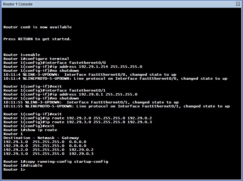 |
| Configuration for Router 1 |
 |
| Configuration for Router 2 |
 |
| Configuration for Router 3 |
To try if there is a successful connection between the three hosts, try to ping the other hosts connected to a specific host. Example, ping Computer B and C, which is connected to Computer A. Ping Computer A and C, which is connected to Computer B. And ping Computer A and B, which is connected to Computer C.
 |
| Computer A pings Computer B |
 |
| Computer A pings Computer C |
 |
| Computer B pings Computer A |
 |
| Computer B pings Computer C |
 |
| Computer C pings Computer A |
 |
| Computer C pings Computer B |
LEARNING AND INSIGHTS
The discussion and activity elaborates the importance and use of IP addresses. Also, the establishment of connection between different computers using the IP configuration concepts is demonstrated by the Network Simulator software so well. I am fascinated with this activity because I am not that knowledgeable in these areas. And the fact that the series of numbers in every IP address symbolizes something, have helped me to understand it better. =)
CONCLUSION
The students learn how to configure local hosts using their respective IP addresses to establish connect with each other. The established connection can be via the router, a server or a switch. Also, the Network Simulator give a concrete example on how to do the configuration virtually. And lastly, it show how the IP addresses are important in every computer around the world.
C:Users/regina>Connection established!
C:Users/regina>Bye! :D


